Raspberry Pi 5 power light solid red, doesn't turn on: how I fixed it
Pi 5 stuck on a solid red LED, never green, won't boot with a good SD card and PSU. It was not a dead PMIC. A 330Ω resistor from pin 1 to GND brought it back.

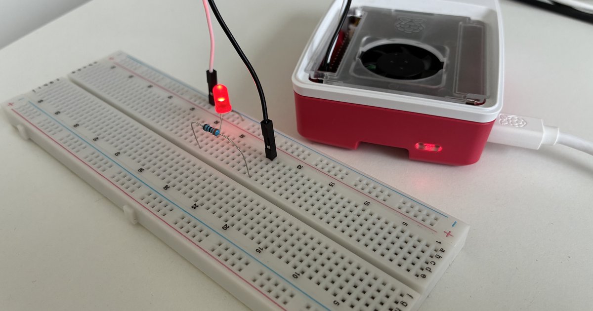
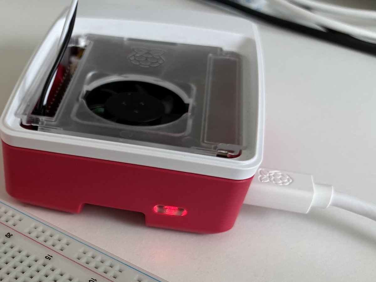
My Raspberry Pi 5 stopped booting one evening. Solid red LED, never any green, no picture, nothing on the network. I spent that whole evening on it and by midnight I had decided the board was dead. The next morning it was back in under a minute, with one resistor and no soldering.
If your Pi 5 looks like the list below, try the fix before you buy a new board. It costs nothing and takes two minutes.
The symptoms
- The status LED is solid red the moment you plug in. It never turns green, never flickers, never blinks a pattern.
- Nothing on HDMI. Nothing on the network. No SSH.
- The SD card is fine. I put it in a laptop, ran a filesystem check, and every boot file was there.
- Two different USB-C power supplies, including the official 27W one. Same result.
- Nothing attached. No HAT, no SD card, no USB, no camera, no fan. Still solid red.
- Unplugging it for 12 hours changed nothing.
- Holding the power button for 30 seconds with the power disconnected, to drain the capacitors, changed nothing.
- Putting the official EEPROM recovery files on the SD card changed nothing. No green blinking.
- USB boot mode (
rpiboot) never saw the Pi. It did not show up as a USB device at all.
If you search for this you will find forum threads where the answer is “PMIC is dead, replace the board.” I read all of them. That is also what I concluded. I was wrong, and the way I was wrong is the useful part.
The two-minute fix
You need one resistor, roughly 330Ω (anything from 220Ω to 1kΩ works), and two jumper wires. Nothing else.
- Power off. Unplug the Pi. Take everything off it: HAT, SD card, USB, camera.
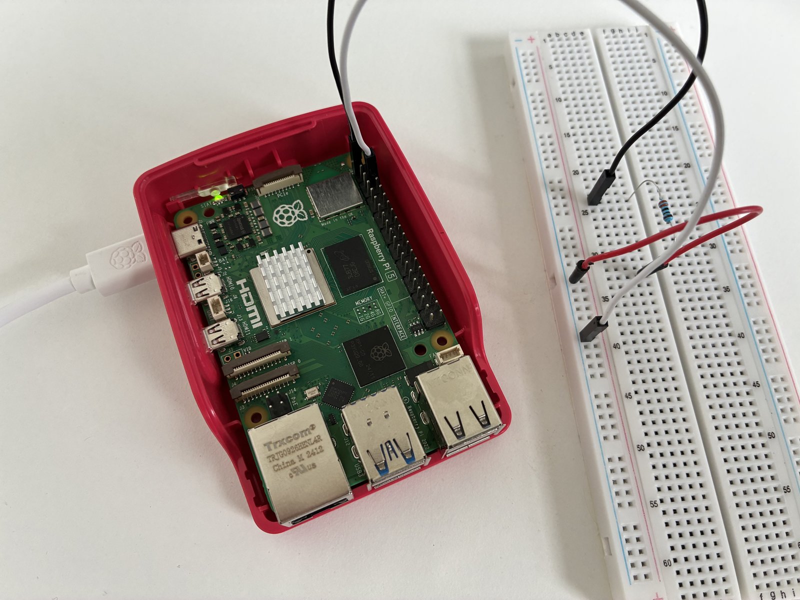
- Hold the Pi so the USB-C socket is on the left and the Ethernet and USB ports are at the bottom. Pin 1 is the top pin of the left column. Pin 6 is the third pin down the right column.
- Wire pin 1 → resistor → pin 6. Pin 1 is the 3.3V rail, pin 6 is ground. You are pulling the 3.3V rail to ground through the resistor. That is the whole trick.
- Plug the power in. Wait three seconds. Unplug.
- Repeat step 4. Mine went green on the third attempt.
- When you see green: leave it, let it boot, then shut it down cleanly. Remove the resistor. From then on it boots on its own.
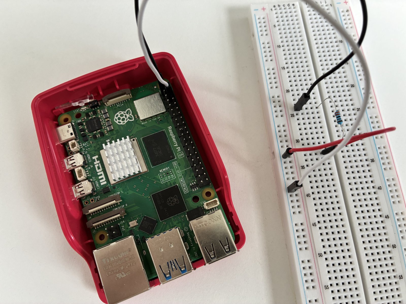
Do not use an LED in place of the resistor. An LED does not conduct below about 1.8V, so it cannot drain a rail that is sitting at half a volt. It has to be a plain resistor.
Why this works
The Pi 5’s power management chip, the PMIC, generates every voltage on the board from the 5V coming in over USB-C. Before it switches a rail on it checks that the rail is at zero. If a rail already has some voltage sitting on it, the PMIC treats that as a fault and refuses to start.
Something had left a small charge on the 3.3V rail. Not enough to light an LED, but enough for the PMIC to see it. Time did not drain it, twelve hours off did not drain it, and the capacitor discharge with the power button did not drain it either, because that discharges the 5V side, not this rail. The resistor drains it directly, at the moment the PMIC is checking.
I am calling that the probable cause rather than the cause. I do not know what put the charge there, and I have no schematic for this PMIC because Raspberry Pi has not published one. What I do know is that a Pi 4 owner on the official forum had the identical symptom, measured 0.9V resting on his 3.3V pin, and fixed it the same way. And that my board has booted normally, without the resistor, on every power cycle since.
How to tell a dead PMIC from one that is refusing to start
This is where I went wrong, and it cost me an evening.
Get an LED and a 330Ω resistor. Wire pin 1 → resistor → LED long leg, LED short leg → pin 6. Plug in and watch the LED.
- The LED never lights. The 3.3V rail never comes up. That is closer to a dead PMIC.
- The LED flashes once and dies. The 3.3V rail comes up and is switched off again within a fraction of a second. That is a working PMIC that is tripping a protection. It is alive. It is refusing.
Mine flashed. I saw it flash and still called it dead, because the forum threads I was reading described the first case, not mine. A chip that starts a rail and then shuts it down is not broken. It is telling you something is wrong on that rail, and the resistor is one way to answer it.
One more test worth doing with two LEDs at once: one on pin 1 (3.3V) and one on pin 2 (5V), both to ground. Watch the 5V one at the instant the 3.3V one flashes. If the 5V LED dips or blinks, your 5V supply path is collapsing under load, and the suspect is a small MOSFET marked G73 on the underside directly beneath the USB-C socket. If the 5V LED stays rock steady, the problem is downstream of the PMIC, which is where the resistor trick applies.
What caused it in my case
The Pi was driving two micro servos on a pan-tilt HAT. The HAT powers the servos straight from the Pi’s own 5V rail, which is how it ships and how the manual tells you to use it.
One servo jammed against a bracket. A stalled servo is close to a short circuit: the motor cannot turn, so it pulls its locked-rotor current, several times what it draws when moving, for as long as it is commanded to hold. That current came through the Pi’s 5V rail and through the PMIC. The Pi shut itself down a while later, sitting idle, and would not come back.
The rule I now follow: motors and servos never run from the Pi’s 5V rail. They get their own supply. Grounds tied together, and only the signal wire goes to the Pi or the HAT. A HAT being designed to power servos from the Pi does not make it safe. There is no fuse, no current limit and nothing between a stalled motor and the chip that makes every voltage on your board.
If the resistor does not bring yours back
Then measure before you decide anything. A multimeter costs about ten euros and it is the difference between guessing and knowing.
- Resting voltage on pin 1, power applied, Pi not booting. Anything above about 0.3V confirms a rail that will not settle, and the fix is a permanent 1kΩ bleed from pin 1 to ground.
- The 5V path. Under the USB-C socket on the underside there is a MOSFET marked G73 with test points TP12 and TP63 next to it. Two documented Pi 5 failures after a short on the 5V rail were this part. Bridging TP12 to TP63 brought those boards back, and the permanent repair was a new MOSFET or a 3A fuse in its place.
- The PMIC itself, the DA9091. If it really is dead, it is now a purchasable part. The Pi Hut sells it in a five-pack for about £11, specifically for repairing Pi 5 boards. Any phone-repair shop with a hot-air station and a microscope can swap it. That is a €15 to €60 repair against a €160 board.
Do not skip straight to a new board. Every one of those is cheaper, and the first one is free.
The short version
- Solid red, never green, good SD card, good PSU, nothing attached: try the resistor before anything else.
- Pin 1 → 330Ω → pin 6. Plug in, three seconds, unplug. Repeat up to five times.
- Green means done. Boot, shut down cleanly, remove the resistor.
- An LED on pin 1 that flashes once means the PMIC is alive. Do not let a forum thread tell you otherwise.
- Keep motors off the Pi’s 5V rail. That is what started this.